

『Flow Meter Display Unit Setup: Calibrating Rate Indicators and Local Signal Processors』Related information(v cone flow meter|rotary gas meter|gallon meter|gear meter|metal tube rotameter|glass tube rotameter|nutating disk meter|transit time ultrasonic flow meter|wedge flow meter|pd meters|hydraulic flow meter|ultrasonic water flow meter|water flow meter|air flow meter|magnetic water flow meter|oxygen flow meter|gas flow meter|argon flow meter|air velocity meter|gasoline flow meter|fuel flow meter|ultrasonic water meter|digital water meter|nitrogen flow meter|solid flow meter|Oxygen tank flow meter|digital water flow meter|diesel fuel flow meter|steam flow meter|02 flow meter|compressed air flow meter|oil flow meter|liquid flow meter)
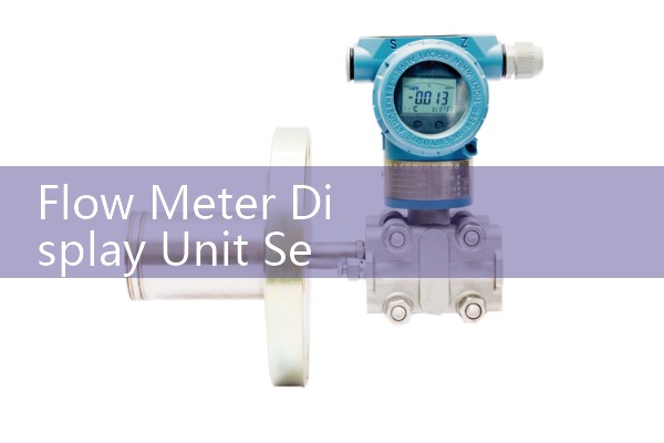
Flow Meter Display Unit Setup: Calibrating Rate Indicators and Local Signal Processors
Quick Answer: A flow meter display unit reads correctly when the input type, K-factor or flow range, and output scaling are all matched. Start with the sensor signal type, set the rate indicator engineering units, then calibrate the retransmission output. Verify the reading with a known flow or a signal simulator before you rely on it for batching or process control.
Most display units from Silver Automation Instruments accept pulse, 4-20 mA analog, or HART digital signals. The setup sequence matters. If the input mode is wrong, the display will show zero, hold a fixed value, or jump. We have seen this on sites in Vietnam, Indonesia, and the Philippines where a flow meter was replaced but the display unit settings were left unchanged.
Confirm the Sensor Signal Type First
Check the flow meter terminal block and the nameplate before you enter the menu. An oval gear flow meter usually sends a pulse output. An electromagnetic flow meter often sends a 4-20 mA analog signal with HART. A Coriolis mass flow meter can send both mass flow and density. The display unit input must match the signal. If you select pulse mode for a 4-20 mA loop, the rate indicator will not count anything useful. If you select 4-20 mA for a pulse signal, the display unit may read a fixed 4 mA or 12 mA as a constant flow.
In practice, most engineers skip this part because they assume the replacement meter uses the same wiring. Do not assume. Check the manual for the meter model. For Silver Instruments electromagnetic flow meters, the signal type is marked on the terminal label inside the housing.
Wire the Display Unit and Local Signal Processor
Use shielded twisted pair cable for analog and pulse loops. Keep the loop length below 300 meters for a standard 24 VDC supply. Route the cable away from VFD motor leads and high voltage trays. Ground the shield only at the display unit or the DCS cabinet side. A local signal processor often sits near the sensor and converts the raw sensor signal to a clean 4-20 mA or pulse output. The display unit then receives the conditioned signal.
For a DN40 electromagnetic flow meter on a water line, the local signal processor may be mounted directly on the sensor. The display unit can be 50 to 200 meters away in the control room. Use a separate 12 to 24 VDC supply if the loop power from the display unit is not enough. Check the wiring before power up. A reversed signal wire is the most common reason for negative flow on a new installation.
Set the Rate Indicator Parameters
The rate indicator needs the correct engineering unit, time base, decimal point, and K-factor. Set the time base first because it changes the scaling. Common units are L/h, m³/h, kg/h, and barrels per day. For a diesel flow meter with a pulse output of 100 pulses per kg, enter a K-factor of 100 if the unit is kg/h. If the unit is L/h, convert using the diesel density at 20 °C, about 0.84 kg/L.
Enter the full scale range and low flow cutoff. A DN25 oval gear flow meter on a light fuel oil line often runs from 0 to 2000 L/h. Set the cutoff at 2 percent of full scale to stop false flow when the pump is stopped. For a steam vortex flow meter, set the cutoff higher, around 5 to 8 percent of full flow, because low pressure steam lines can create noise at low velocity.
Calibrate the 4-20 mA Retransmission From the Display Unit
After the display reading is stable, calibrate the output signal to the PLC or DCS. Many display units have a forced output or loop test function. Use it to send 4 mA and 20 mA. Check that the control system engineering range matches the display unit range. If the display unit sends 0 to 5000 kg/h and the DCS is set to 0 to 10000 kg/h, the flow will read half of the actual value. We have seen this on a batch control system in Thailand. The fix was to match the range in both devices.
The analog outp
Field Verification With Known Flow
Do not trust a bench calibration alone. Run the pump at one stable flow and compare the display unit value with a calibrated reference meter or a bucket and stopwatch on small lines. On a DN50 water line at 10 m³/h, a 60 second bucket test should collect about 166.7 liters. If the value is off, adjust the K-factor or the span and retest. For hot fluid lines, allow the temperature to stabilize before you adjust the reading. A thermal mass flow meter also needs the correct gas type selected in the display unit. Methane and nitrogen have different heat transfer properties. The reading can be 20 to 30 percent off if the gas type is wrong.
Common Setup Mistakes and Field Fixes
A common mistake is setting the damping time too low. A damping of 0.1 seconds on a positive displacement flow meter will make the display jump with every gear pass. Set damping to 2 to 5 seconds for a stable 4-20 mA signal. Another mistake is leaving a low flow cutoff at zero on a magnetic flow meter. Air bubbles or pipe vibration can make the display show flow when the line is not running. A cutoff of 0.5 to 2 percent of full scale is enough for water and wastewater service. For conductive liquids above 20 µS/cm, a Silver Instruments electromagnetic flow meter works well with a short straight run and proper grounding.
A paint manufacturer in Southeast Asia chased a 50 kg/h batching error for two days. The flow meter sensor was fine. The display unit had a 0.1 second damping setting and a low cutoff of zero. After changing the damping to 3 seconds and the cutoff to 1 percent, the batch weight returned to within 0.5 percent.
FAQ: Flow Meter Display Unit Setup
Q: How do I set the K-factor in a flow meter display unit?
A: Enter the K-factor in pulses per unit volume or mass. The display unit converts the input frequency into a flow rate. For a turbine meter with 2450 pulses per liter, enter 2450 and set the unit to L/h.
Q: Why does my rate indicator show negative flow?
A: In most cases the signal wires are reversed. Check the polarity of the 4-20 mA loop or the pulse input. Some display units also allow you to invert the signal in software.
Q: Can one display unit show rate and total at the same time?
A: Yes. Most Silver Instruments rate indicators have a dual display. The top line shows the rate in kg/h or L/h and the bottom line shows the total in m³ or kg. You can reset the total with a front panel key or a password protected menu.
Q: What is the difference between a rate indicator and a local signal processor?
A: A rate indicator displays flow. A local signal processor converts a sensor signal to a standard 4-20 mA or pulse signal. Some units do both. The local signal processor is usually closer to the sensor and is often specified for hazardous areas like ATEX Zone 1.
Q: How often should we calibrate a flow meter display unit?
A: For custody transfer or batch charging, verify the display unit every 6 to 12 months. Use a signal simulator to check the input and a known flow to check the sensor. For general process control, a yearly check is enough.
For technical help with flow meter display unit setup, send us your pipe size (DN), flow range, signal type, process temperature, and pressure (bar). Our engineers can help with rate indicator settings, local signal processor wiring, and calibration. Contact Silver Instruments at Tel: +86-25-68650347, Whatsapp: +86-25-52155837, or WeChat: +86 15365082610.
 Hot News
 Related AD