

『Electromagnetic Flow Meter Accuracy Factors: How to Reduce Pipe Interference』Related information(v cone flow meter|rotary gas meter|gallon meter|gear meter|metal tube rotameter|glass tube rotameter|nutating disk meter|transit time ultrasonic flow meter|wedge flow meter|pd meters|hydraulic flow meter|ultrasonic water flow meter|water flow meter|air flow meter|magnetic water flow meter|oxygen flow meter|gas flow meter|argon flow meter|air velocity meter|gasoline flow meter|fuel flow meter|ultrasonic water meter|digital water meter|nitrogen flow meter|solid flow meter|Oxygen tank flow meter|digital water flow meter|diesel fuel flow meter|steam flow meter|02 flow meter|compressed air flow meter|oil flow meter|liquid flow meter)
Electromagnetic Flow Meter Accuracy Factors: How to Reduce Pipe Interference
Quick Answer
Pipe interference is a common cause of electromagnetic flow meter accuracy drift, noisy output, and false readings on empty pipes. Keep at least 5D of straight pipe upstream and 2D downstream, ground the meter body correctly on lined or plastic pipes, and install the meter in a full pipe section with no high point air pockets. These practical steps keep readings stable within ±0.2 to ±0.5 percent of rate on most DN15 to DN600 lines.
Where Pipe Interference Comes From
Electromagnetic flow meters measure the voltage generated when a conductive liquid moves through a magnetic field. The voltage is small. On a DN50 line with water at 2 m/s, the electrode signal is often below 1 mV. Any external noise or disturbed flow profile shifts that signal enough to create error.
Pipe interference is not one single thing. In practice, it shows up in four site conditions. First, an elbow, tee, valve, or pump is too close to the meter inlet. The liquid swirls or flows faster on one side. The meter assumes a symmetric velocity profile. That assumption breaks. Second, the meter body is not grounded to the process pipe or to earth. This is common on plastic pipes, cement pipes, and internally coated steel pipes. Third, the meter is mounted at a high point or a free-drain section. Air bubbles collect near the electrodes. Fourth, nearby variable frequency drives, motors, or cathodic protection systems leak stray current into the line.
We have seen this on customer sites many times. A water treatment plant in Vietnam installed a DN200 electromagnetic flow meter only 3D after a 90-degree elbow. The reading jumped 3 to 4 percent during afternoon pump cycles. After the meter was moved to 8D upstream and the grounding rings were added, the error dropped below 0.5 percent.
Straight Pipe Runs and Flow Conditioning
The cheapest way to reduce pipe interference is to give the meter a stable flow profile. For most standard electromagnetic flow meters, use 5D of straight pipe upstream and 2D downstream. For a DN100 meter, that means 500 mm of clean run before the meter and 200 mm after the meter. If the upstream disturbance is a control valve or a pump, use 10D upstream. If the fluid has a very low conductivity below 20 µS/cm, use even longer runs because the signal is weaker.
Do not place the meter directly after a partially open butterfly valve. The jet flow can hit half the electrode and create a strong bias. If short straight runs are unavoidable, install a flow conditioner or choose a meter with a shorter inlet requirement. Some Silver Instruments models can work with 3D upstream because of a reinforced electrode and a more stable excitation circuit.
Here is the thing. Most engineers skip the downstream run because they think it does not matter. It does. A valve or elbow after the meter can create backflow or pressure pulsation that affects the signal. Keep at least 2D downstream, especially on slurry or high viscosity fluids.
Grounding and Lining Choices
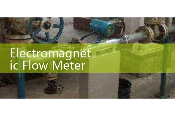
Grounding is not optional. On metal pipes, connect the meter body to the process pipe and to earth. On plastic pipes, fiberglass pipes, or internally coated pipes, install grounding rings or a grounding electrode. Without a proper ground, solid state converters often show fluctuating flow when pumps start or stop.
For wastewater, chemical, and desalination plants, we recommend stainless steel groundi
Calibration and Verification After Installation
After installation, check the empty pipe detection and the electrode resistance. For a remotely mounted converter, keep the signal cable shorter than 30 meters and use shielded twisted pair cable. Route the cable away from high voltage motors and VFD cables. A good rule on site is to keep at least 300 mm separation between the magmeter cable and any power cable.
Perform a real flow verification with a known volume or a clamp on reference meter if possible. Do not rely only on the factory calibration certificate. Site conditions change the accuracy. A chemical plant in Thailand improved a DN80 acid dosing line from ±1.5 percent error to below ±0.3 percent just by re-routing the signal cable away from a pump power line.
Recommended Meter Sizing for Stable Accuracy
Select the meter size by line size first, not by a future expansion guess. An oversized meter on a low flow line runs below 0.3 m/s. That low velocity makes the meter more sensitive to pipe noise and coating. A general sizing rule is to keep the normal flow between 1 and 5 m/s. For water and wastewater, an easy target is 2 to 3 m/s. For abrasive slurry, keep velocity below 3 m/s to protect the liner. For chemical dosing with low flow, a smaller DN meter often gives better accuracy than a full pipe size meter with a reducer.
Silver Automation Instruments supplies electromagnetic flow meters from DN15 to DN2000 for water, wastewater, chemical, food and beverage, and marine services. Send your pipe size (DN), flow range, pressure (bar), temperature (°C), and liner requirement to our team. Tel: +86-25-68650347, Whatsapp: +86-25-52155837, WeChat: +86 15365082610.
FAQ
What is the minimum straight pipe length for an electromagnetic flow meter?
For standard meters, keep 5D upstream and 2D downstream. For a DN50 meter that is 250 mm before and 100 mm after. Use 10D upstream if the meter is after a pump or control valve.
Why does my electromagnetic flow meter show a reading when the pipe is empty?
This often comes from poor grounding or a missing empty pipe detection setting. Air gaps between the electrodes and the liquid break the signal loop. The converter may interpret noise as flow. Enable empty pipe detection and install the meter in a low point or a full pipe section.
Can I install an electromagnetic flow meter on a plastic pipe?
Yes, but you must install grounding rings or a meter with a grounding electrode. Without grounding, stray current enters the signal circuit and the accuracy drops.
What is the best liner for wastewater and sludge?
Rubber and polyurethane liners work well for wastewater and sludge. They resist abrasion and are cost effective up to 80 °C. For chemical wastewater, PTFE or PFA is safer.
What flow velocity gives the most stable electromagnetic flow meter accuracy?
Aim for 1 to 5 m/s. The best range for most water and chemical lines is 2 to 3 m/s. Below 0.3 m/s the signal is weak and noise is high.
 Hot News
 Related AD